> For the complete documentation index, see [llms.txt](https://docs.premium-modellbau.de/premium-modellbau-portal-fuer-anleitungen/llms.txt). Markdown versions of documentation pages are available by appending `.md` to page URLs; this page is available as [Markdown](https://docs.premium-modellbau.de/premium-modellbau-portal-fuer-anleitungen/matek/matek-systems-ubersicht/matek-flightcontroller/h7a3-slim.md).
# H7A3-SLIM
**Artikelnr.:** PM-7030 | **HAN:** H7A3-SLIM
[Zum Premium-Modellbau Shop](https://www.premium-modellbau.de/search?sSearch=PM-7030)
#### **Specifications**
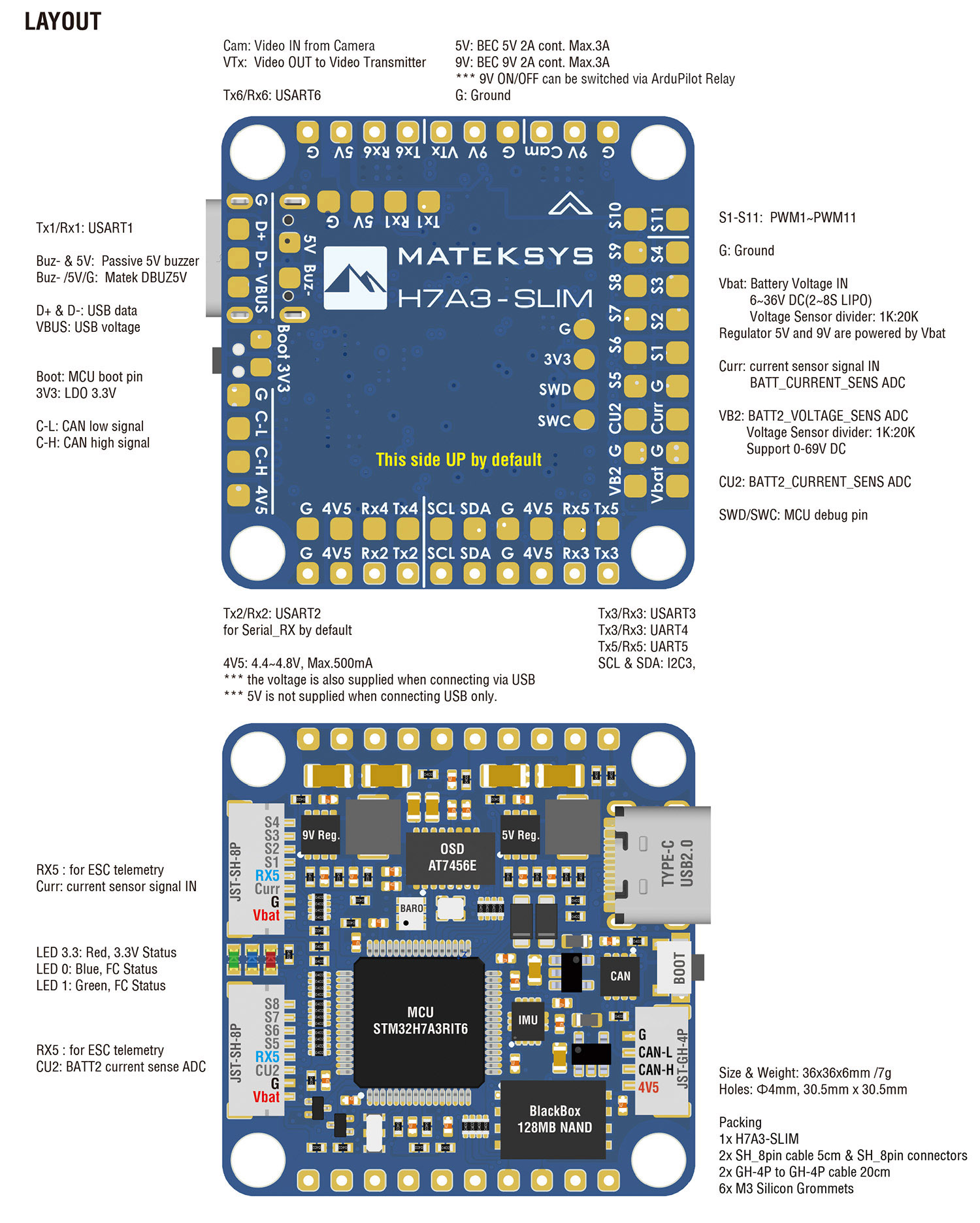
* MCU: STM32H7A3RIT6, 280MHz Cortex-M7, 1.4MB RAM, 2MB Flash
* IMU: ICM42688P
* Baro: SPL06-001
* OSD: AT7456E
* Blackbox: 128MB Flash (1G-bit NAND)
* 6x Uarts (1,2,3,4, 5, 6) with built-in inversion.
* 11x PWM outputs
* 1x I2C
* 1x CAN
* 4x ADC (VBAT, Current, VB2, Cur2)
* 3x LEDs for FC STATUS (Blue, Red) and 3.3V indicator(Red)
* USB Type-C(USB2.0)
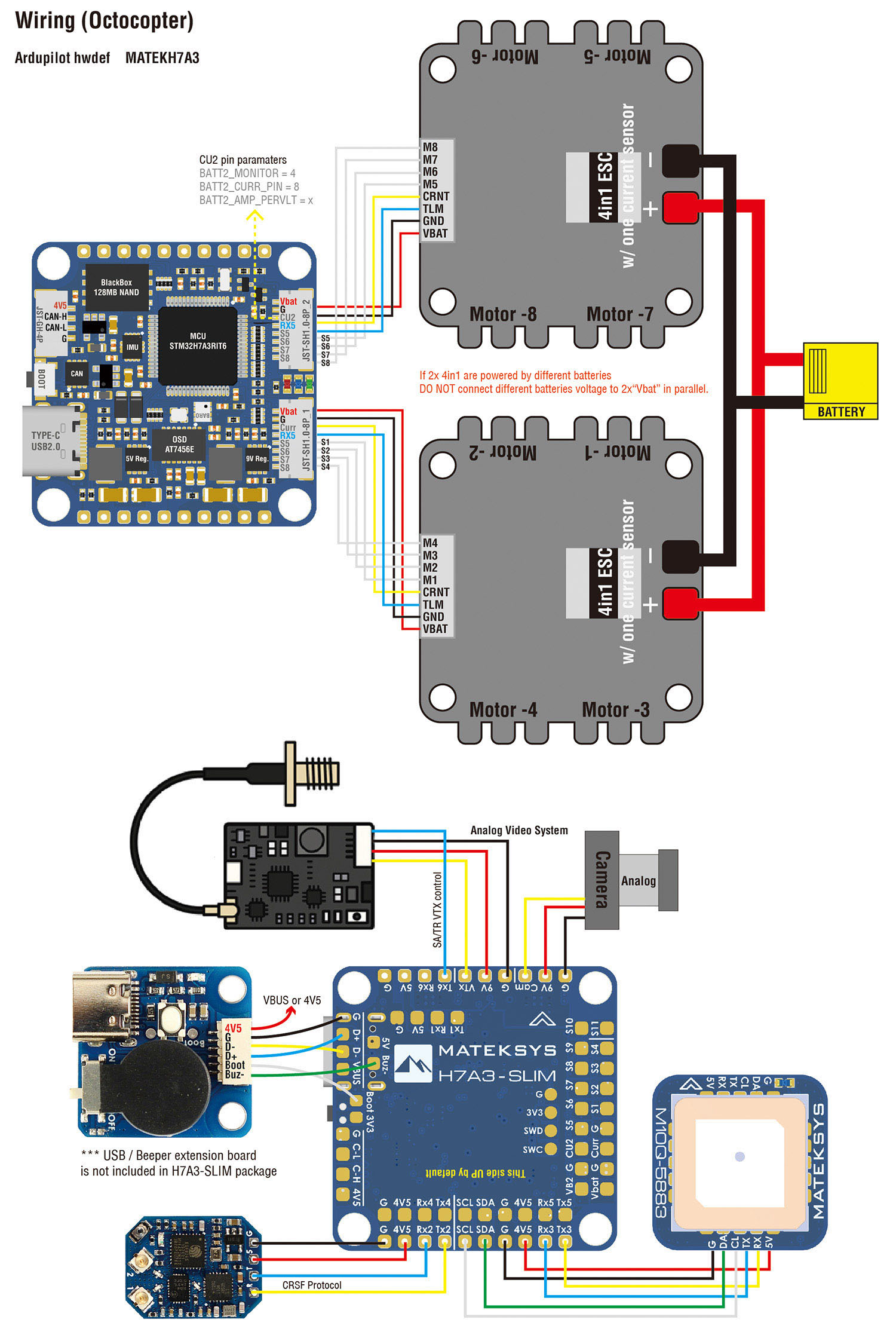
* 8x PWM outputs on 2x JST-SH1.0\_8pin connector for 2x 4in1 ESC
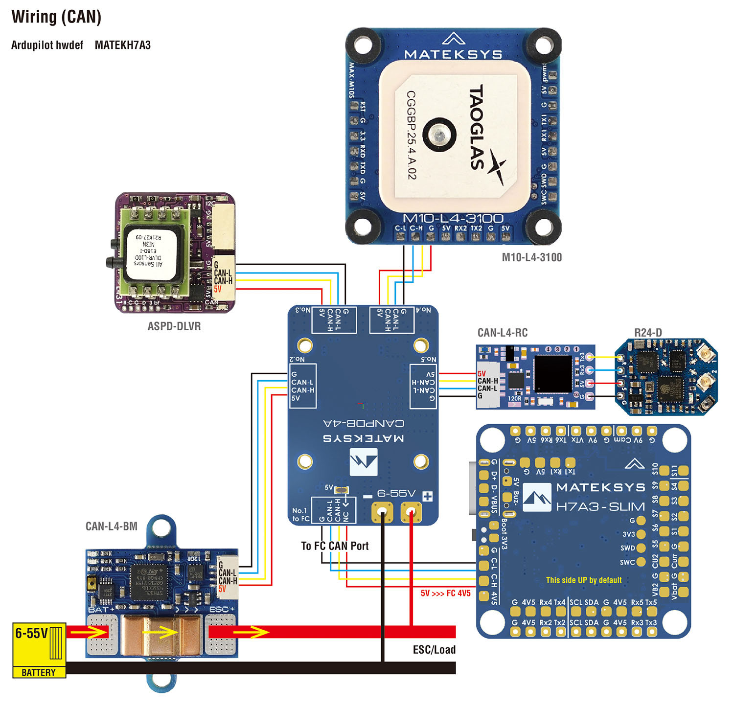
* 1x JST-GH1.25\_4pin connector (5V/CAN-H/CAN-L/G)
* 9V output ON/OFF switchable
* Digital video OSD is supported by any spare UART
#### Power
* Vbat Input: 6~~36V (2~~8S LiPo)
* BEC: 5V 2A cont. (Max.3A)
* BEC: 9V 2A cont. (Max.3A)
* LDO 3.3V: Max.200mA
* No Current Sensor built-in
* ADC VB2 pad supports Max. 69V (voltage divider: 1K:20K)
#### **FC Firmware**
* ArduPilot: MATEKH7A3 (4.6 or newer)
* ArduPlane
* ArduCopter
* [Flashing with STM32CubeProgrammer](https://www.mateksys.com/?p=6905)
#### **Physical**
* Mounting: 30.5 x 30.5mm, Φ4mm with Grommets Φ3mm
* Dimensions: 36 x 36 x 5 mm
* Weight: 7g
* 3D step [H7A3-SLIM\_step.zip](https://github.com/Premium-Modellbau/premium-modellbau-docs/blob/main/matek/matek-systems-ubersicht/downloads/other/H7A3-SLIM_step.zip)
#### **Including**
* 1x H7A3-SLIM
* 6x Silicon grommets M4 to M3
* 2x JST-SH1.0\_8pin cable, 5cm, & 8pin connectors
* 1x JST-GH-4P to JST-GH-4P cable for CAN port, 20cm
Layout

Wiring (Octocopter)
Wiring (CAN)
ArduPilot mapping
| | | | | | | |
| ------------------------------------------------------------------------------------------------------------------------------------------------------------------------------------------------------------------------------------------------------------------------------------------------------------------------------------------------------------------------------------------------------------------------------------------------------------------------------------------ | --------------------------------------- | ------------------- | ----------------------------------- | -------------------------------- | --------------------------------- | ------- |
| ArduPilot | | | | | | |
| PWM | S1 | PWM1 GPIO50 | 5 V tolerant I/O | TIM1\_CH2 | DMA/Bi-DShot | Group1 |
| S2 | PWM2 GPIO51 | 5 V tolerant I/O | TIM1\_CH3 | DMA/Bi-DShot | | |
| S3 | PWM3 GPIO52 | 5 V tolerant I/O | TIM2\_CH1 | DMA/Bi-DShot | Group2 | |
| S4 | PWM4 GPIO53 | 5 V tolerant I/O | TIM2\_CH2 | DMA/Bi-DShot | | |
| S5 | PWM5 GPIO54 | 5 V tolerant I/O | TIM3\_CH3 | DMA/Bi-DShot | Gourp3 | |
| S6 | PWM6 GPIO55 | 5 V tolerant I/O | TIM3\_CH4 | DMA/Bi-DShot | | |
| S7 | PWM7 GPIO56 | 5 V tolerant I/O | TIM3\_CH1 | DMA/Bi-DShot | | |
| S8 | PWM8 GPIO57 | 5 V tolerant I/O | TIM3\_CH2 | DMA/Bi-DShot | | |
| S9 | PWM9 GPIO58 | 5 V tolerant I/O | TIM4\_CH1 | DMA/DShot | Group4 | |
| S10 | PWM10 GPIO59 | 5 V tolerant I/O | TIM4\_CH2 | DMA/DShot | | |
| S11 | PWM11 GPIO60 | 5 V tolerant I/O | TIM16\_CH1 | DMA/DShot | Group5 | |
| PWM1\~PWM11 are Dshot and PWM capable. However, mixing Dshot and normal PWM operation for outputs is restricted into groups, ie. enabling Dshot for an output in a group requires that ALL outputs in that group be configured and used as Dshot, rather than PWM outputs. If servo and motor are mixed in same group, make sure this group run lowest PWM frequency according to the servo specification. That is to say. If Servo support Max. 50Hz, ESC must run at 50Hz in this group. | | | | | | |
| PINIO | 9V switch | GPIO81 | | RELAY1\_PIN | | 81 |
| ADC | Vbat pad | BATT\_VOLTAGE\_SENS | 6\~36V | BATT\_VOLT\_PIN BATT\_VOLT\_MULT | | 10 21.0 |
| Curr pad | BATT\_CURRENT\_SENS | 0\~3.3V | BATT\_CURR\_PIN BATT\_AMP\_PERVLT | | 11 X | |
| VB2 Pad | BATT2\_VOLTAGE\_SENS | 0\~69V | BATT2\_VOLT\_PIN BATT2\_VOLT\_MULT | | 18 21.0 | |
| CU2 Pad | BATT2\_CURRENT\_SENS | 0\~3.3V | BATT2\_CURR\_PIN BATT2\_AMP\_PERVLT | | 8 X | |
| I2C | SCL/SDA | I2C3 | 5V tolerant I/O | on board Baro SPL06-001 | Address | 0x76 |
| Digital Airspeed I2C MS4525 DLVR-L10D | ARSPD\_BUS ARSPD\_TYPE ARSPD\_TYPE | 0 1 9 | | | | |
| Magnetometer | COMPASS\_AUTODEC | 1 | | | | |
| CAN | C-H/C-L | CAN2 | 5V tolerant I/O | CAN | CAN\_D1\_PROTOCOL CAN\_P1\_DRIVER | 1 1 |
| CAN GPS CAN Compass CAN Airspeed sensor | GPS\_TYPE COMPASS\_TYPEMASK ARSPD\_TYPE | 9 0 8 | | | | |
| UART | USB | USB | | console | SERIAL0\_PROTOCOL | 2 |
| TX1 RX1 | USART1 w/DMA | 5 V tolerant I/O | Telemetry | SERIAL1\_PROTOCOL | 2 | |
| TX2 RX2 | USART2 w/DMA | 5 V tolerant I/O | RC input/Receiver | SERIAL2\_PROTOCOL | 23 | |
| TX3 RX3 | USART3 w/DMA | 5 V tolerant I/O | GPS | SERIAL3\_PROTOCOL | 5 | |
| TX4 RX4 | UART4 w/o DMA | 5 V tolerant I/O | Spare | SERIAL4\_PROTOCOL | -1 | |
| TX5 RX5 | UART5 w/o DMA | 5 V tolerant I/O | Spare | SERIAL5\_PROTOCOL | -1 | |
| TX6 RX6 | USART6 w/o DMA | 5 V tolerant I/O | Spare | SERIAL6\_PROTOCOL | -1 | |
#### RC INPUT
RC input is configured on the USART2(SERIAL2). It supports all serial RC protocols. SERIAL2\_PROTOCOL=23 by default.
* PPM is not supported.
* CRSF requires Tx2 & Rx2 connection, and set SERIAL2\_OPTIONS to “0” (default).
* SBUS/DSM/SRXL connects to the Rx2 pin, but SBUS requires that the SERIAL2\_OPTIONS be set to “3”.
* FPort requires connection to Tx2, and set SERIAL2\_OPTIONS to “7”. If Telemetry doesn’t work, try set SERIAL7\_OPTIONS = 135.
* SRXL2 requires a connection to Tx2, and automatically provides telemetry. Set SERIAL2\_OPTIONS to “4”.
* Any UART can be used for RC system connections in ArduPilot also, and is compatible with all protocols except PPM. See [Radio Control Systems](https://ardupilot.org/copter/docs/common-rc-systems.html#common-rc-systems) for details.
#### ArduPilot Relay(PINIO)
* 9V output ON by default
* PC13 PINIO1 OUTPUT GPIO(81) //9V power switche.g.
* RELAY\_PIN 81 // PINIO1 GPIO
* RC7\_OPTION 28 //Relay On/Off, Use CH7 of Transmitter to set 9V ON/OFF
The configured feature will be triggered when the auxiliary switch’s pwm value becomes higher than 1800. It will be deactivated when the value falls below 1200.
Check the pwm value sent from the transmitter when the switch is high and low using the Mission Planner’s Initial Setup >> Mandatory Hardware >> Radio Calibration screen. If it does not climb higher than 1800 or lower than 1200, it is best to adjust the servo end points in the transmitter.