> For the complete documentation index, see [llms.txt](https://docs.premium-modellbau.de/premium-modellbau-portal-fuer-anleitungen/llms.txt). Markdown versions of documentation pages are available by appending `.md` to page URLs; this page is available as [Markdown](https://docs.premium-modellbau.de/premium-modellbau-portal-fuer-anleitungen/matek/matek-systems-ubersicht/matek-flightcontroller/h7a3-wing.md).
# H7A3-WING
**Artikelnr.:** PM-7221 | **HAN:** H7A3-WING
[Zum Premium-Modellbau Shop](https://www.premium-modellbau.de/search?sSearch=PM-7221)
\_x000D\_\* MCU: STM32H7A3RIT6, 280MHz Cortex-M7, 1.4MB RAM, 2MB Flash \_x000D\_\* IMU: ICM42688P \_x000D\_\* Baro: SPL06-001 \_x000D\_\* OSD: AT7456E \_x000D\_\* Blackbox: MicroSD socket \_x000D\_\* I2C digital power monitor \_x000D\_ \_x000D\_
\_x000D\_\* 6x Uarts (1,2,3,4, 5, 6) with built-in inversion. \_x000D\_\* 11x PWM outputs \_x000D\_\* 1x I2C \_x000D\_\* 1x CAN \_x000D\_\* 4x ADC (VBAT, Current, VB2, Cur2) \_x000D\_\* 3x LEDs for FC STATUS (Blue, Red) and 3.3V indicator(Red) \_x000D\_\* USB/Beep Extender with Type-C(USB2.0) \_x000D\_\* 2x JST-GH1.25\_4pin connector for CAN and I2C \_x000D\_ \_x000D\_
\_x000D\_\* 9V/12V output ON/OFF switchable \_x000D\_ \_x000D\_
\_x000D\_\* Digital video OSD is supported by any spare UART \_x000D\_ \_x000D\_
#### Regulators
\_x000D\_
\_x000D\_\* Vbat Input: 9~~30V (3~~6S LiPo) \_x000D\_\* BEC 5V/4v5: 2.5A cont. /3A peak \_x000D\_\* BEC 9V/12V: 2A cont. /3A peak \_x000D\_\* BEC Vx: 8A cont. /12A Peak, output 5V Default, 6V or 7.2V option. \_x000D\_\* LDO 3.3V: Max.200mA \_x000D\_ \_x000D\_
#### I2C digital power monitor
\_x000D\_
\_x000D\_\* No calibration required. \_x000D\_\* Current sensing resistor: 0.00025 ohm \_x000D\_\* Load current on current sensing resistor: 100A(Continuous), 164A(Burst) \_x000D\_\* Voltage accuracy: ± 0.1% \_x000D\_\* Current accuracy: ± 2% \_x000D\_\* INA2xx I2C address: 0x45 (69) \_x000D\_ \_x000D\_
\_x000D\_\* Parameters\_x000D\_ \_x000D\_+ BATT\_MONITOR ->21 (INA2xx) \_x000D\_+ BATT\_SHUNT -> 0.00025 \_x000D\_+ BATT\_MAX\_AMPS -> 164 \_x000D\_+ BATT\_I2C\_BUS -> 0 default \_x000D\_+ BATT\_I2C\_ADDR -> 0 default (or 69) \_x000D\_\_x000D\_ \_x000D\_ \_x000D\_
#### **FC Firmware**
\_x000D\_
\_x000D\_\* ArduPilot: MATEKH7A3 (4.6 or newer) \_x000D\_\* ArduPlane \_x000D\_\* ArduCopter \_x000D\_\* [Flashing with STM32CubeProgrammer](https://www.mateksys.com/?p=6905) \_x000D\_ \_x000D\_
#### **Physical**
\_x000D\_
\_x000D\_\* Mounting: 30.5 x 30.5mm, F4mm with Grommets F3mm \_x000D\_\* Dimensions: 54 x 36 x 13 mm \_x000D\_\* Weight: 30g with USB extender \_x000D\_ \_x000D\_
#### **Including**
\_x000D\_
\_x000D\_\* 1x H7A3-WING \_x000D\_\* 1x USB(Type-C)/Beep (Passive buzzer) Extender with 6pin cable \_x000D\_\* 1x 20cm JST-SH-6P to JST-SH-6P cable for USB extender. \_x000D\_\* 2x 20cm JST-GH-4P to JST-GH-4P cable for CAN & I2C port \_x000D\_\* 1x Rubycon ZLH 35V 470uF capacitor \_x000D\_\* Dupont 2.54 pins **(Board is shipped unsoldered)** \_x000D\_ \_x000D\_ \_x000D\_
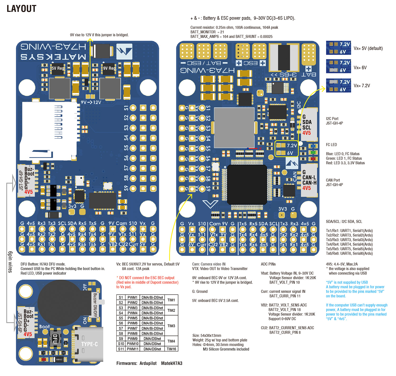
Layout

\_x000D\_
\_x000D\_
ArduPilot mapping
\_x000D\_\_x000D\_| | | | | | | | | --- | --- | --- | --- | --- | --- | --- | |\_x000D\_ ArduPilot | | | | | | |\_x000D\_ \_x000D\_|\_x000D\_ PWM |\_x000D\_ S1 |\_x000D\_ PWM1 GPIO50 |\_x000D\_ 5 V tolerant I/O |\_x000D\_ TIM1\_CH2 |\_x000D\_ DMA/Bi-DShot |\_x000D\_ Group1 |\_x000D\_ \_x000D\_|\_x000D\_ S2 |\_x000D\_ PWM2 GPIO51 |\_x000D\_ 5 V tolerant I/O |\_x000D\_ TIM1\_CH3 |\_x000D\_ DMA/Bi-DShot |\_x000D\_ \_x000D\_|\_x000D\_ S3 |\_x000D\_ PWM3 GPIO52 |\_x000D\_ 5 V tolerant I/O |\_x000D\_ TIM2\_CH1 |\_x000D\_ DMA/Bi-DShot |\_x000D\_ Group2 |\_x000D\_ \_x000D\_|\_x000D\_ S4 |\_x000D\_ PWM4 GPIO53 |\_x000D\_ 5 V tolerant I/O |\_x000D\_ TIM2\_CH2 |\_x000D\_ DMA/Bi-DShot |\_x000D\_ \_x000D\_|\_x000D\_ S5 |\_x000D\_ PWM5 GPIO54 |\_x000D\_ 5 V tolerant I/O |\_x000D\_ TIM3\_CH3 |\_x000D\_ DMA/Bi-DShot |\_x000D\_ Group3 |\_x000D\_ \_x000D\_|\_x000D\_ S6 |\_x000D\_ PWM6 GPIO55 |\_x000D\_ 5 V tolerant I/O |\_x000D\_ TIM3\_CH4 |\_x000D\_ DMA/Bi-DShot |\_x000D\_ \_x000D\_|\_x000D\_ S7 |\_x000D\_ PWM7 GPIO56 |\_x000D\_ 5 V tolerant I/O |\_x000D\_ TIM3\_CH1 |\_x000D\_ DMA/Bi-DShot |\_x000D\_ \_x000D\_|\_x000D\_ S8 |\_x000D\_ PWM8 GPIO57 |\_x000D\_ 5 V tolerant I/O |\_x000D\_ TIM3\_CH2 |\_x000D\_ DMA/Bi-DShot |\_x000D\_ \_x000D\_|\_x000D\_ S9 |\_x000D\_ PWM9 GPIO58 |\_x000D\_ 5 V tolerant I/O |\_x000D\_ TIM4\_CH1 |\_x000D\_ DMA/DShot |\_x000D\_ Group4 |\_x000D\_ \_x000D\_|\_x000D\_ S10 |\_x000D\_ PWM10 GPIO59 |\_x000D\_ 5 V tolerant I/O |\_x000D\_ TIM4\_CH2 |\_x000D\_ DMA/DShot |\_x000D\_ \_x000D\_|\_x000D\_ S11 |\_x000D\_ PWM11 GPIO60 |\_x000D\_ 5 V tolerant I/O |\_x000D\_ TIM16\_CH1 |\_x000D\_ DMA/DShot |\_x000D\_ Group5 |\_x000D\_ \_x000D\_|\_x000D\_ PWM1~~PWM11 are Dshot and PWM capable. However, mixing Dshot and normal PWM operation for outputs is restricted into groups, \_x000D\_ ie. enabling Dshot for an output in a group requires that ALL outputs in that group be configured and used as Dshot, rather than PWM outputs. \_x000D\_ If servo and motor are mixed in same group, make sure this group run lowest PWM frequency according to the servo specification. \_x000D\_ That is to say. If Servo support Max. 50Hz, ESC must run at 50Hz in this group. | | | | | |\_x000D\_ \_x000D\_|\_x000D\_ PINIO |\_x000D\_ 9V switch |\_x000D\_ GPIO81 |\_x000D\_ |\_x000D\_ RELAY1\_PIN | |\_x000D\_ 81 |\_x000D\_ \_x000D\_|\_x000D\_ ADC |\_x000D\_ Vbat pad |\_x000D\_ BATT\_VOLTAGE\_SENS |\_x000D\_ 0~~36V |\_x000D\_ BATT\_VOLT\_PIN \_x000D\_ BATT\_VOLT\_MULT | |\_x000D\_ 10 \_x000D\_ 21.0 |\_x000D\_ \_x000D\_|\_x000D\_ Curr pad |\_x000D\_ BATT\_CURRENT\_SENS |\_x000D\_ 0~~3.3V |\_x000D\_ BATT\_CURR\_PIN \_x000D\_ BATT\_AMP\_PERVLT | |\_x000D\_ 11 \_x000D\_ X |\_x000D\_ \_x000D\_|\_x000D\_ VB2 Pad |\_x000D\_ BATT2\_VOLTAGE\_SENS |\_x000D\_ 0~~69V |\_x000D\_ BATT2\_VOLT\_PIN \_x000D\_ BATT2\_VOLT\_MULT | |\_x000D\_ 18 \_x000D\_ 21.0 |\_x000D\_ \_x000D\_|\_x000D\_ CU2 Pad |\_x000D\_ BATT2\_CURRENT\_SENS |\_x000D\_ 0\~3.3V |\_x000D\_ BATT2\_CURR\_PIN \_x000D\_ BATT2\_AMP\_PERVLT | |\_x000D\_ 8 \_x000D\_ X |\_x000D\_ \_x000D\_|\_x000D\_ I2C |\_x000D\_ SCL/SDA |\_x000D\_ I2C3 |\_x000D\_ 5V tolerant I/O |\_x000D\_ on board Baro SPL06-001 |\_x000D\_ I2C Address |\_x000D\_ 0x76 |\_x000D\_ \_x000D\_|\_x000D\_ on board Baro INA2XX |\_x000D\_ I2C Address |\_x000D\_ 0x45 |\_x000D\_ \_x000D\_|\_x000D\_ Digital Airspeed I2C \_x000D\_ MS4525 \_x000D\_ DLVR-L10D |\_x000D\_ ARSPD\_BUS \_x000D\_ ARSPD\_TYPE \_x000D\_ ARSPD\_TYPE |\_x000D\_ 0 \_x000D\_ 1 \_x000D\_ 9 |\_x000D\_ \_x000D\_|\_x000D\_ Magnetometer |\_x000D\_ COMPASS\_AUTODEC |\_x000D\_ 1 |\_x000D\_ \_x000D\_|\_x000D\_ CAN |\_x000D\_ C-H/C-L |\_x000D\_ CAN2 |\_x000D\_ 5V tolerant I/O |\_x000D\_ CAN |\_x000D\_ CAN\_D1\_PROTOCOL \_x000D\_ CAN\_P1\_DRIVER |\_x000D\_ 1 \_x000D\_ 1 |\_x000D\_ \_x000D\_|\_x000D\_ CAN GPS \_x000D\_ CAN Compass \_x000D\_ CAN Airspeed sensor |\_x000D\_ GPS\_TYPE \_x000D\_ COMPASS\_TYPEMASK \_x000D\_ ARSPD\_TYPE |\_x000D\_ 9 \_x000D\_ 0 \_x000D\_ 8 |\_x000D\_ \_x000D\_|\_x000D\_ UART |\_x000D\_ USB |\_x000D\_ USB |\_x000D\_ |\_x000D\_ console |\_x000D\_ SERIAL0\_PROTOCOL |\_x000D\_ 2 |\_x000D\_ \_x000D\_|\_x000D\_ TX1 RX1 |\_x000D\_ USART1 w/DMA |\_x000D\_ 5 V tolerant I/O |\_x000D\_ Telemetry |\_x000D\_ SERIAL1\_PROTOCOL |\_x000D\_ 2 |\_x000D\_ \_x000D\_|\_x000D\_ TX2 RX2 |\_x000D\_ USART2 w/DMA |\_x000D\_ 5 V tolerant I/O |\_x000D\_ RC input/Receiver |\_x000D\_ SERIAL2\_PROTOCOL |\_x000D\_ 23 |\_x000D\_ \_x000D\_|\_x000D\_ TX3 RX3 |\_x000D\_ USART3 w/DMA |\_x000D\_ 5 V tolerant I/O |\_x000D\_ GPS |\_x000D\_ SERIAL3\_PROTOCOL |\_x000D\_ 5 |\_x000D\_ \_x000D\_|\_x000D\_ TX4 RX4 |\_x000D\_ UART4 w/o DMA |\_x000D\_ 5 V tolerant I/O |\_x000D\_ Spare |\_x000D\_ SERIAL4\_PROTOCOL |\_x000D\_ -1 |\_x000D\_ \_x000D\_|\_x000D\_ TX5 RX5 |\_x000D\_ UART5 w/o DMA |\_x000D\_ 5 V tolerant I/O |\_x000D\_ Spare |\_x000D\_ SERIAL5\_PROTOCOL |\_x000D\_ -1 |\_x000D\_ \_x000D\_|\_x000D\_ TX6 RX6 |\_x000D\_ USART6 w/o DMA |\_x000D\_ 5 V tolerant I/O |\_x000D\_ Spare |\_x000D\_ SERIAL6\_PROTOCOL |\_x000D\_ -1 |\_x000D\_ \_x000D\_\_x000D\_
\_x000D\_
#### RC INPUT
\_x000D\_
RC input is configured on the USART2(SERIAL2). It supports all serial RC protocols. SERIAL2\_PROTOCOL=23 by default.
\_x000D\_\_x000D\_
\_x000D\_\* PPM is not supported. \_x000D\_\* CRSF requires Tx2 & Rx2 connection, and set SERIAL2\_OPTIONS to “0” (default). \_x000D\_\* SBUS/DSM/SRXL connects to the Rx2 pin, but SBUS requires that the SERIAL2\_OPTIONS be set to “3”. \_x000D\_\* FPort requires connection to Tx2, and set SERIAL2\_OPTIONS to “7”. If Telemetry doesn’t work, try set SERIAL7\_OPTIONS = 135. \_x000D\_\* SRXL2 requires a connection to Tx2, and automatically provides telemetry. Set SERIAL2\_OPTIONS to “4”. \_x000D\_\* Any UART can be used for RC system connections in ArduPilot also, and is compatible with all protocols except PPM. See [Radio Control Systems](https://ardupilot.org/copter/docs/common-rc-systems.html#common-rc-systems) for details. \_x000D\_ \_x000D\_\_x000D\_
#### ArduPilot Relay(PINIO)
\_x000D\_\_x000D\_
\_x000D\_\* 9V/12V output ON by default \_x000D\_ \_x000D\_
\_x000D\_\* RELAY1\_FUNCTION 1 \_x000D\_\* RELAY1\_PIN 81 // PINIO1 GPIO \_x000D\_\* RC7\_OPTION 28 //Relay1 On/Off, Use CH7 of Transmitter to set 9V/12V ON/OFF \_x000D\_ \_x000D\_
The configured feature will be triggered when the auxiliary switch’s pwm value becomes higher than 1800. It will be deactivated when the value falls below 1200.
\_x000D\_
Check the pwm value sent from the transmitter when the switch is high and low using the Mission Planner’s Initial Setup >> Mandatory Hardware >> Radio Calibration screen. If it does not climb higher than 1800 or lower than 1200, it is best to adjust the servo end points in the transmitter.
\_x000D\_
\_x000D\_
Tips & Notes
\_x000D\_\* set **LOG\_BACKEND\_TYPE = 1** (File) for SD card logging. \_x000D\_\* set **BATT\_MONITOR = 21 , BATT\_SHUNT = 0.00025, BATT\_MAX\_AMPS = 164** for using the built-in I2C digital power monitor. \_x000D\_ \_x000D\_